
The �鶹Լ��’s first three UHD HDR series (Planet Earth II, Blue Planet II and Dynasties) were all produced by the Natural History Unit using the Hybrid Log-Gamma (HLG) high dynamic range (HDR) format, and made available on-demand on �鶹Լ�� iPlayer. But right from the start, HLG was developed with live television production in mind – it is robust to the video processing associated live TV (e.g. mezzanine compression, image filtering and resizing) and does not require metadata.
However, it's not only the video processing chain that complicates live TV production. Major sports events frequently use around 40 cameras, and the �鶹Լ��'s coverage of the wedding of the Duke and Duchess of Sussex last year used 76 cameras, combined with a further 30 cameras from Sky. Sports productions also rely heavily on specialist cameras such as netcams (cameras mounted within the football goal posts), robocams (small robotic cameras in confined spaces), (traversing a sports pitch on wires), and super and ultra slo-motion cameras. Those specialist cameras are expected to remain standard dynamic range (SDR) and standard colour gamut () for many years to come.
To integrate those specialist cameras seamlessly into an HDR production, high-quality SDR to HDR format conversion is essential. This is further complicated by the wider colour gamut that's available with HDR-TV.
For most broadcasters, as the majority of viewers are still watching in SDR, the SDR picture quality must not be impacted in any way by the HDR aspects of the production. So, for the 2018 Royal Wedding, FIFA World Cup and Wimbledon Centre Court trials, a parallel HDR/SDR workflow was deployed. HDR cameras provided HDR and SDR outputs, with each sent to a dedicated HDR or SDR production switcher (vision mixer), with one slaved to the other.
Details are given in my Royal Wedding blog. However, such parallel workflows are complex and expensive as they require a great deal more equipment and it can be difficult to synchronise the various signal paths. For UHD HDR production to become mainstream, it is essential that only a single UHD HDR workflow is deployed, and a high-quality SDR output is automatically derived from the UHD HDR programme. So our 2019 FA Cup Trials have focussed on developing a single UHD HDR workflow, that can deliver stunning pictures to both our UHD HDR iPlayer service and the conventional broadcast and streamed SDR services.
�鶹Լ�� 2019 FA Cup Coverage
At the , the EBU found that shading (racking) cameras using an HDR monitor created HDR images that were difficult to convert to SDR, as they exploited too wide a range of exposures. So, for the FA Cup trials, the �鶹Լ��'s SDR and HDR cameras were all shaded using an SDR monitor.
Quarter Final - Millwall vs Brighton & Hove Albion
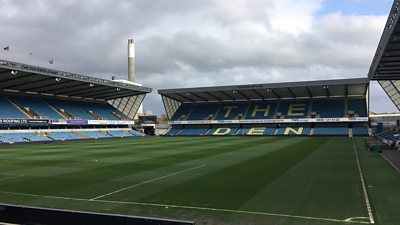
Our first FA Cup trial was at the Quarter Final game between Millwall and Brighton at 'The Den' on 17th March 2019. Even though the SDR �鶹Լ�� One feed was derived from the UHD HDR production, the UHD for this first event was not distributed to the public. However, at Millwall, we learnt that our goal of delivering stunning HDR and SDR pictures that pleased both us and the Vision Supervisors would be harder to achieve than expected.
Rather than shading the HDR cameras via an HDR to SDR converter, in order to reduce the total number of HDR to SDR converters, we tried shading the cameras using their dedicated SDR outputs – just as we had done for The Royal Wedding, and Wimbledon had done for their Centre Court coverage last year. However, unlike those events, football coverage makes extensive use of the camera's artistic 'painting' controls, to deliver a particular 'punchy' and 'colourful' football 'look'. To increase the contrast in the SDR image, detail in the shadows is often crushed, and detail in the highlights clipped. Some additional colour saturation may also be applied. The artificial contrast isn't necessary on bright HDR screens, so the SDR football 'look' is almost the exact opposite of what HDR TV was designed to deliver!
To achieve the desired look in the SDR programme output (derived from the HDR signal chain), we needed to make extensive use of the cameras' HDR painting controls. But in common with many other cameras, those controls worked differently on the camera's HDR and SDR outputs. So, the Vision Engineers had to work hard to ensure that the pictures reaching SDR audiences resembled those they were seeing on their own SDR shading monitors.
Semi-Final - Manchester City vs Brighton & Hove Albion
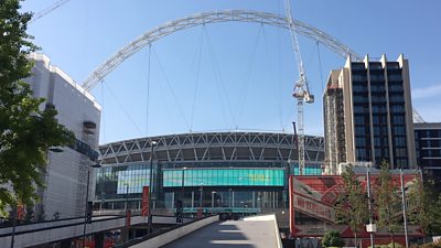
The second trial was at the FA Cup Semi-Final between Manchester City and Brighton & Hove Albion at Wembley on 6th April. For this trial, which did go out in UHD on �鶹Լ�� iPlayer, we made a significant improvement to the camera shading workflow.
To avoid the problems we saw with shading at Millwall, this time the HDR cameras were shaded in SDR but using the HLG backwards compatible picture displayed on an SDR BT.2020 (gamma 2.2) monitor; thereby allowing the Vision Engineers to monitor the cameras' HDR outputs, from which the �鶹Լ�� One SDR feed was derived. Although the pictures closely matched those of the dedicated HDR to SDR converter feeding the main �鶹Լ�� One transmission output (when viewed on a reference gamma 2.4 display), there were still small but visible differences in the SDR highlights between the two. Those differences limited the Vision Engineers' comfortable exposure range. So, when it came to the FA Cup Final, huge efforts were made to source sufficient converters to allow all cameras to be shaded via a dedicated HDR to SDR converter.
Final - Manchester City vs Watford
Our last trial was at the itself, between Manchester City and Watford at Wembley on 18th May. At each stage of the tournament, the production had grown in complexity, and we refined the workflow based on what we had learnt previously. The FA Cup Final was particularly complicated as the �鶹Լ�� was the host broadcaster, responsible for providing the main match coverage to other rights-holding broadcasters.
A simplified diagram of the production architecture that we developed for the Final is shown in the figure below. The �鶹Լ��'s production facilities were actually split over two ; one supporting the main match cameras, and a second supporting the �鶹Լ��'s studio presentation facilities. For clarity, the figure combines those two operations into a single production, as if there were only a single UHD HDR production switcher.
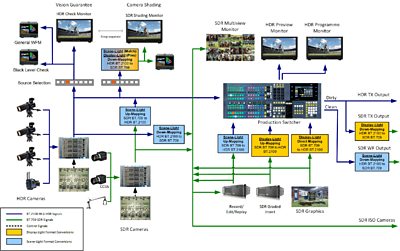
You will see different types of conversion being used in different places:
- Direct-mapping refers to the process of simply placing SDR content into an HDR signal container, at the correct signal level. Typically 100% of the SDR signal is mapped to 'HDR Reference White', defined in as 75% HLG signal.
- Up-mapping is similar, except the highlights within the SDR signal are given a small 'boost' so that the SDR signal better matches the appearance of a native HDR signal.
- Down-mapping is the reverse process. An HDR signal is converted to SDR, by compressing the HDR signal highlights. An artistic choice is made between the amount of detail that is preserved in the HDR highlights and the overall brightness of the SDR image (including any embedded graphics).
- Hard-clipping can also be used for HDR to SDR conversion. Hard clipping can deliver brighter SDR images and graphics, but any highlights captured by the HDR cameras are lost in the conversion.
Scene-Light vs. Display-Light Conversion
The diagram also shows two different ways of performing the format conversions – display-light in yellow, and scene-light in blue. For a successful HDR production, it is important to understand the differences between them and when to use them. That is most easily explained by considering the theoretical end-to-end television chain, illustrated below.
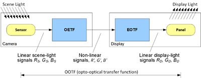
Light collected by the camera lens is focused onto the camera sensor and converted into three linear light signals, RS, GS and BS. The linear light signals are proportional to the red, green and blue light falling on the camera sensor, so are referred to as scene-light signals. The scene-light signals are then converted to non-linear signals R', G', B' using the camera's opto-electronic transfer function (OETF).
The OETF improves the noise performance of the end-to-end chain, by providing a better match between the noise introduced by quantization in the production chain and the human visual system. The R', G', B' signals are then passed to the display where an electro-optical transfer function (EOTF) converts the non-linear signals to the linear display-light signals RD, GD, BD which feed the panel.
Overall the TV system has a non-linear opto-optical transfer function (OOTF), which is the concatenation of the camera OETF and display EOTF. The OOTF is designed to ensure that the displayed pictures appear subjectively similar to the scene in front of the camera, by compensating for the changes in the sensitivity of the human visual system as the eye adapts to its surroundings and the display. A 'gamma law' where the displayed light is proportional to the relative scene-light raised to a power (gamma), is most often used:

Each HDR or SDR format has its own OETF and EOTF pair. So, the resulting OOTF that determines the displayed appearance (or 'look') of a given scene, is different for each format.
A display-light format conversion uses the EOTFs of the relevant formats, and a scene-light conversion uses the corresponding OETFs.
Display-Light SDR/HDR Conversions
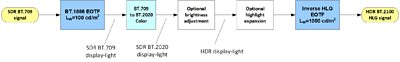
Display-light conversions are calculated by deriving the light produced by a reference display. They preserve the original displayed 'look' of content (colour and tone) after conversion to the new format. So, they are generally used for graded content and graphics, where it is important that those aspects are maintained.
An example of a display-light SDR to HDR converter is shown in the diagram below.
Scene-Light SDR/HDR Conversions
Scene-light conversions are calculated by deriving the light that would have fallen on a camera sensor, for a given signal. They are used for matching cameras working in different formats, as the light falling on the camera sensor would have been the same, regardless of the production format. But as the displayed 'look' of each format is different, scene-light conversions will alter the displayed hue, tone and saturation of objects in the scene.
An example of scene-light conversion of BT.709 signals to BT.2100 HLG is shown below.
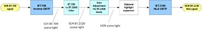
In practice, artistic adjustments (known as 'painting') and the camera white balance and sharpness (detail) compensation, are applied within the camera to modify the scene-light signal. So the format conversions actually work on a 'quasi-scene-light' signal, that represents the light that would need to have fallen on the camera sensor to deliver the desired image.
More details can be found in the ITU-R's '' . �鶹Լ�� R&D's format conversion LUTs were used for all conversions at the FA Cup trials, running in hardware from a variety of manufacturers.
Production Architecture
As , in addition to the main UHD HDR output, we had to provide two further SDR programme outputs, shown in the diagram:
- A 'dirty' (meaning with embedded �鶹Լ�� graphics) output to feed our �鶹Լ�� One SDR services. As it was important that the �鶹Լ�� graphics were the same colour and saturation in both our UHD HDR and SDR services, a display-light conversion was used.
- A 'clean' (meaning without graphics) 'world feed' output to pass on to other broadcasters covering the event. As at least one of those broadcasters had their own SDR cameras at the grounds, it was important that this conversion matched those cameras. So a scene-light conversion was used.
We're keen that the HDR production also benefits SDR viewers, so down-mapping (which preserves some of the HDR highlights) rather than hard clipping was used for the conversion on both SDR outputs.
The �鶹Լ�� coverage used 41 cameras in total, of which 12 were SDR and the remainder HDR. Signals from the SDR cameras were converted to HDR to pass through the switcher using scene-light up-mapping, to ensure a good match with the native HDR cameras. However, all 41 cameras also needed to be provided to other broadcasters as independent SDR ISO (isolated) feeds. To ensure HDR and SDR cameras matched, scene-light down-mapping from HDR to SDR was used for the HDR cameras.
Those same SDR ISO signals were also used to feed the multiview monitors in the two production galleries. However, large consumer UHD HDR TVs were provided for the switchers' programme and preview outputs, allowing the Directors to see their output in the highest quality HLG HDR.
As we needed to record so many camera feeds simultaneously (including the high frame rate cameras used for slow-motion) the record/replay servers were limited to 8-bit SDR recording. Re-configuring them for 10-bit HDR would have had a big impact on the number of record/replay channels available. To ensure that the SDR action replays exactly matched the live cameras, complementary scene-light up-mapping (which was the exact inverse of the HDR camera SDR down-mapping) was used on the server outputs. To help ensure that the correct converters were deployed in the correct signal paths, a wipe was set-up on the switcher between the live camera output and its equivalent via the record/replay server route. When all was working correctly, the only differences seen between the two signal paths were in the extreme HDR highlights that were clipped via the servers – a remarkably good colour and tone match was achieved overall.
Like any big sports production, the FA Cup Final included graded SDR programme inserts, such as the title sequence and archive material. At the Quarter Final and Semi-Finals, these were replayed into the production switcher via a dedicated display-light up-mapper; thereby preserving their 'look' in both the main HDR and SDR programme outputs. However, this added considerable operational complexity, as different replay lines had to be selected for the graded programme inserts (display-light) and action replays (scene-light). The differences between the display-light and the scene-light up-mapper that we used are small – to match cameras, the scene-light up-mapping is slightly less saturated overall, the biggest difference being in the reds. So, to reduce the risk of operational errors during the final, all replay lines were switched to scene-light conversion. That operational change has not been reflected in the architecture diagram.
To preserve the colour of the SDR graphics, a display-light direct mapping to HLG HDR was used on the input to the graphics keyer within the production switcher. Direct-mapping is preferred for graphics, to ensure they do not appear too bright on an HDR screen. If the graphics are too bright, it can often make the underlying HDR video look dull in comparison.
The one down-side of direct mapping of the graphics is that after down-mapping back to SDR (known as round-tripping) for the main output, the signal level for SDR graphics white is usually reduced to between 85% and 90% SDR signal. The reduction in graphics level creates some headroom for the compressed HDR highlights but does not conform to current practice in SDR production. As an alternative, hard clipping from HDR to SDR can be used on the programme output, which can place the HDR graphics at 100% SDR signal. But most of the benefits of the HDR production will be lost to SDR viewers, as highlights captured by the HDR cameras will be clipped and lost.
Finally, the diagram shows the SDR shading monitor fed via a dedicated HDR to SDR down-mapper. The HDR monitor only used as an occasional 'check monitor' during the live transmission. Display-light down-mapping was used for camera shading in the OB truck supporting the �鶹Լ�� presentation ('pres') studio, as the display-light HDR to SDR conversion for �鶹Լ�� One was considered its main SDR output. Scene-light down-mapping was used for shading in the OB truck supporting the main match ('match') coverage, as the scene-light HDR to SDR conversion for the World Feed was considered its SDR main output. In practice the differences are small and within the usual artistic tolerances for football, so either could have been used.
SDR cameras were always shaded via an up-mapper and down-mapper, as illustrated in the diagram. So the Vision Engineers were again viewing an identical picture to the truck's main SDR output.
Key Lessons and Future Work
Camera shading
In practice, the HDR and SDR camera outputs from HDR cameras seldom track one another precisely across all settings. So it is difficult to achieve satisfactory results for challenging productions such as football unless the HDR cameras are shaded via a dedicated HDR to SDR down-mapper. It makes very little difference whether the down-mapper is a scene-light or display-light variant, but to avoid confusion amongst operational staff, it is helpful if the shading down-mapper is the same type as the one used for the OB truck's main SDR output.
Mixing HDR and SDR cameras
By default, SDR BT.709 delivers pictures that are more colourful than nature, and with shadow detail slightly crushed – originally intended to mask the camera sensor noise. We have grown accustomed to the standard BT.709 look, and many find it artistically pleasing. The colour saturation and shadow detail may be increased further for programmes such as football, by using the camera's painting controls.
A different approach was taken for the design of HLG HDR, in part because artistic preferences vary by region. So, as I have reported previously, HLG was designed to deliver very 'natural' HDR images that closely resemble nature. Artistic adjustments can then be added using a camera's 'painting' controls, or in colour grading for non-live production. However, as mentioned above, we found that currently the HDR and SDR camera painting controls are implemented differently. So, if they are heavily used, as is often the case for football, it becomes harder to match HDR and SDR cameras over the whole exposure range. The Vision Engineers found that they had to worry about colour balance as well as just exposure.
HDR to SDR conversion
When converting from HDR to SDR, the contrast within an image is reduced. That leads to an apparent softening of the SDR image, as the rate of change of the displayed luminance (i.e. luminance gradient) around edges is reduced. Some hardware converters can compensate by adding 'detail' or sharpness back into the SDR image, but not all converters offer that useful feature. So, it may be necessary to compensate for the subjective loss of sharpness in the image elsewhere in the signal chain.
Line-up signals
Colour bars are frequently used to check the integrity of the end-to-end signal chain before a live transmission. They are typically fed into the production switcher, along with a lip-sync test, and measured at various points along the signal chain.
Unfortunately, even the BT.709 bars within the HDR Colour Bar pattern are distorted by many HDR to SDR down-mappers, as their signal level is too high. So it is difficult to predict what values should be measured on the SDR outputs. To address that problem, we are now testing a special set of colour bars that have been designed to be robust to format conversion. Details can be found in Annex 2 of our conversion LUT documentation.
HDR Monitoring
Lastly, we found that in the confined space of an outside broadcast truck, it is not always practicable to achieve complete separation between the SDR and HDR monitors in the Vision Engineering area.
As critical monitoring is in SDR, to avoid the camera shaders being affected by glare from an HDR check monitor, the nominal peak luminance of the HLG HDR monitor might be reduced, for example to 600 cd/m2 (requiring a display gamma of 1.10) to reduce the disturbance. HDR Reference White on a 600 cd/m2 HLG display is 138 cd/m2. So a 600 cd/m2 HLG monitor can provide a more reasonable brightness match to typical SDR production monitor.
Summary
Through our three UHD FA Cup production trials, we have tested and refined an HDR workflow that can deliver both stunning UHD HDR pictures, and high-quality SDR pictures that even improve upon those produced by a native SDR production workflow. No one watching the �鶹Լ�� One HD (SDR) coverage appeared to notice that it was derived from a UHD HDR production, which was exactly what we set out to achieve.
There's still some work to do based on what we learnt from these most recent trials – work on signal line-up; proving the workflow for cameras from other manufacturers, and some small improvements to make in our own format conversion LUTs. But with the help of �鶹Լ�� Sport and our production partners, we've established a credible UHD HDR live production workflow that can deliver a step-change improvement in the home viewing experience.
-

Broadcast and Connected Systems section
Broadcast & Connected Systems primarily focuses on how �鶹Լ�� content reaches our viewers through broadcast and Internet delivery. This involves the whole broadcast chain from playout, through coding and distribution to consumption on the end-user's device. Our work typically covers a period from now through to 3 years out from deployment.