Key points
Circuit diagrams are used to show how electrical A part of a circuit eg a battery, motor, lamp, switch or wire. are connected in a An electrical circuit is made up of components, which are connected together using wires..
Individual circuit components are represented using circuit symbols.
Ammeters are used to measure the Current isô aô flow of charges.ô It is measured in amps (A). flowing through components. Voltmeters are used to measure the The amount of energy transferred by each unit of charge passing between two points of a circuit. The unit for potential difference is the volt (V). across components.
Video - Introduction to circuits
For electricity to flow, everything needs to be connected in a big ring. Itãs called a circuit.
For example, the lights in most houses and flats are part of a circuit controlled by the consumer unit, where power enters the house.
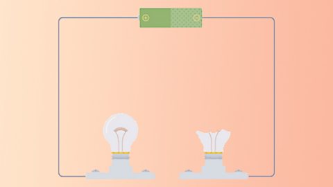
We can see how circuits work, and represent them with some simple diagrams, using basic electrical components like these.
You start with a cell, or combination of cells. These could be batteries, solar panels, or a power supply connected to the mains - anything that can provide power to our circuit.
A wire from the cell can then be connected to a component like a bulb.
And to complete the circuit you need to connect it back to the other side of the cell.
Ah! There we go!
You can put all kinds of other components in the circuit, to be powered by the cell.
Like a motor.
Or you can even put in a switch that can temporarily break the circuit.
We can also add in some components that measure the current and the potential difference.
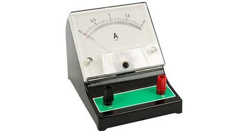
An ammeter tells you the current, or the flow of charge through the circuit, measured in amps. In this circuit itãs nought point two three amps.
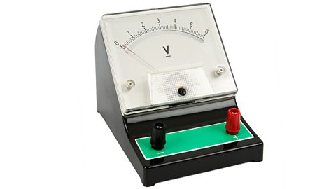
And a voltmeter measures the potential difference in volts, which is the difference in energy between two parts of a circuit. Across the cell here, we can see it is one point four one volts.
Because the flow of electricity is invisible, it can be pretty tricky to imagine whatãs going on inside all the tiny wires. So it helps to think of an electrical circuit a bit like the central heating system in a house. We call this comparison a model.
The cell or battery is like the boiler and the pump, pushing hot water around. The current flowing through the wires is like hot water going through the pipes.
And the radiators are where we can feel the results of that circulating hot water, just like we see the results of the electricity flowing through the bulb.
And, of course, the central heating system has to be connected back to the boiler, or else youãd have water everywhere.Donãt worry though, if an electrical circuit isnãt connected back to the cell, it just doesnãt work. You donãt get electricity spilling out of the wires!
So the next time you switch on a light, you can imagine the flow of electricity, like hot water, looping around a huge circuit.
Can you answer these questions based on the video?
Which component provides power to the circuit?
Which component measures the current or flow of charge through the circuit?
A cell, battery (combination of cells) or power supply provides power to the circuit.
An ammeter measures the current (flow of charge) through the circuit. Current is measured in units called amps.
Circuit symbols
Electrical components, like A device which spins when current flows through it. Motors are used in fans, food processors and many other devices. and A component which produces light when current flows through it. Lamps are commonly known as light bulbs., can be connected together to form a An electrical circuit is made up of components, which are connected together using wires..
A circuit diagram shows how the components are connected.
Use straight lines to show the A thin piece of metal which electrical current can flow through. Wires are used to connect components together. Wires are often covered in plastic insulation. Wires are also known as cables or leads. andCircuit symbols are used to represent components when drawing a circuit diagram. to represent each component.
Cells and batteries
Cells
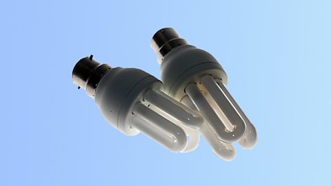
Cells provide energy which enables electrons to flow through wires and components, when connected into an electrical circuit. Cells can be connected together to form batteries. provide the energy for many electrical devices to function - like torches, mobile phones and laptops. Cells come in different sizes and shapes.
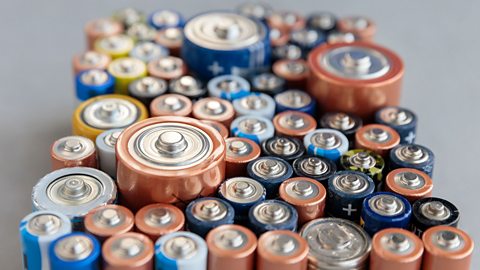
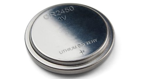
Most cells are cylindrical, including button cells which are often used to power small devices like watches and thermometers. Most cells cannot be reused after they are empty, although some can be recharged and used many times.
The most common type of cell is the electrochemical cell which uses chemical reactions to transfer energy.
Batteries
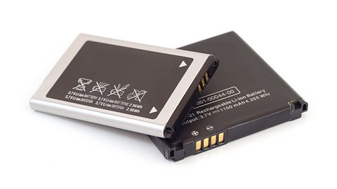
Many people mistakenly use the word battery when they mean Cells provide energy which enables electrons to flow through wires and components, when connected into an electrical circuit. Cells can be connected together to form batteries..
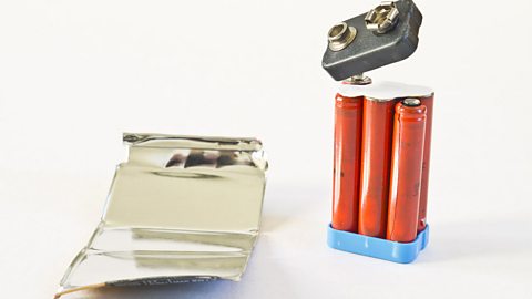
A battery is made of two or more cells connected together.

Never open a battery yourself. There is a risk of explosion and you could come into contact with the hazardous chemicals inside the battery.
The circuit symbol for a battery is made by joining two or more cell symbols.
These images show the circuit symbols for a two-cell battery and a three-cell battery.
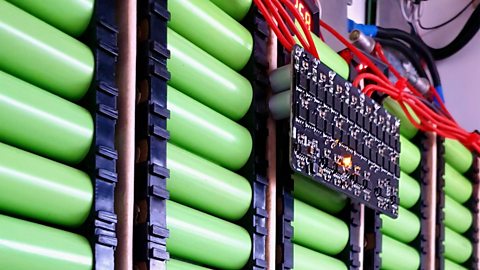
Batteries can also be used to power electric vehicles, or to store energy from solar panels which can later be used to power your home.
These batteries can contain many thousands of cells.
Did you know?
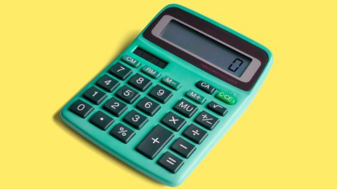
Not all cells use chemical reactions to generate electricity. Solar cells, also known as photovoltaic cells (or PV cells), use sunlight. They are often used to power small devices such as a calculator.
Circuit diagrams
A circuit diagram uses circuit symbols to represent each component in the circuit.
This picture shows a simple An electrical circuit is made up of components, which are connected together using wires. with a Cells provide energy which enables electrons to flow through wires and components, when connected into an electrical circuit. Cells can be connected together to form batteries. and a A component which produces light when current flows through it. Lamps are commonly known as light bulbs..
This circuit diagram shows the same circuit, but uses circuit symbols to represent the cell, bulb and wires.
How to draw a circuit diagram
To draw an accurate circuit diagram, follow these steps:
Step 1 - Draw the circuit symbols.
Step 2 - Draw all the wires to connect the symbols together. Use a ruler and do not let the wires cross each other.
Always try to make the A thin piece of metal which electrical current can flow through. Wires are used to connect components together. Wires are often covered in plastic insulation. Wires are also known as cables or leads. straight lines so it is easier to see how the components are connected together.
Current
When a circuit has been connected correctly, an electrical flows. Just like a current in a river is a flow of water, an electrical current in a wire is a flow of Negatively charged particles which orbit atoms. Electrons can flow through wires to form an electrical current.
The more electrons flow through a wire each second, the greater the current.
The units of current are called The unit of measurement of current. Ampere is often shortened to amp., often shortened to amps. Use the symbol A to represent amperes, eg a current of 1.5 amps can be written as 1.5 A.
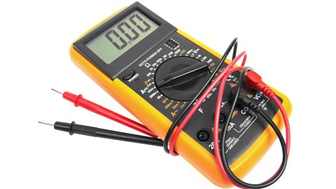
Current is measured using a device called an A device used to measure current. Ammeters are connected in series with components.. Some types of ammeter have a pointer on a dial, but most have a digital display.
Ammeters are connected into a circuit using wires, like any other component.
An ammeter is connected in A way of connecting components in a circuit. A series circuit has all the components in one loop connected by wires, so there is only one route for current to flow. , meaning it is connected in a loop with all the other components.
The ammeter can be placed anywhere in a series circuit.
Did you know?
The units of current are named after Andrûˋ-Marie Ampû´re - a French mathematician and physicist who is one of the founders of the science of electromagnetism.
Potential difference
Potential difference is the amount of energy transferred by each unit of charge passing between two points of a circuit.
The unit of potential difference is the volt. The symbol for volts is V. A potential difference of 1.5 volts can be written as 1.5 V.
Potential difference is also commonly called ãvoltageã.
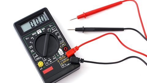
Potential difference is measured using a device called a A device used to measure potential difference. Voltmeters are connected in parallel with components.. Just like A device used to measure current. Ammeters are connected in series with components., some types have a pointer on a dial, but most have a digital display.
The potential difference produced by a Cells provide energy which enables electrons to flow through wires and components, when connected into an electrical circuit. Cells can be connected together to form batteries. or Two or more cells connected together forms a battery. can be measured by connecting the leads of the voltmeter to each side of the cell or battery.
Unlike an ammeter, a voltmeter is connected in A way of connecting components in a circuit. A parallel circuit has components on separate branches, so the current can take different routes around the circuit. ã meaning it is on its own separate branch of the circuit.
It cannot be connected in A way of connecting components in a circuit. A series circuit has all the components in one loop connected by wires, so there is only one route for current to flow. (in the same loop as the other components).
In this diagram, each cell produces a potential difference of 1.5 V, so a three-cell battery produces a potential difference of 4.5 V.
The potential difference across a component can be measured by connecting the leads of the voltmeter on each side of the component.
The diagram below shows how a voltmeter can be connected to measure the potential difference across a lamp.
Did you knowãÎ?
The units of potential difference are named after Alessandro Volta, the Italian physicist who invented the electric battery.
Test your knowledge
Quiz
Play the Atomic Labs game! game
Try out practical experiments in this KS3 science game.

More on Electricity
Find out more by working through a topic
- count7 of 11
- count8 of 11
- count9 of 11

- count10 of 11