Electric charge, current and circuits
Electric charge
Some particles carry an The electrical state of an object, which can be positively charged or negatively charged.. In electric wires these particles are These are one of the particles that atoms are made from. They have a negative charge. Charge can be positive or negative. For example, protons are positively charged and electrons are negatively charged. . We get an electric current when these charged particles move from place to place.
Electric current
An An electric current is a flow of charged particles in one direction. In solids, an electric current is the flow of free electrons in one direction. is a flow of charge, and in a wire this will be a flow of electrons. We need two things for an electric current to flow:
- something to transfer energy to the electrons, such as a battery or power pack
- a complete path for the electrons to flow through (an An electrical circuit is made up of components, which are connected together using wires.)
The simplest complete circuit is a piece of wire from one end of a battery to the other. An electric current can flow in the wire from one end of the battery to the other, but nothing useful happens. The wire just gets very hot and the battery loses stored internal energy â it âgoes flatâ and stops working.
To do something useful with the electric current, you need to put an electrical A part of a circuit eg a battery, motor, lamp, switch or wire. into the circuit, that can use the current in a useful way.
You usually add a Switches can be used to make or break connections in a circuit. Current can only flow if the switch is closed. to the circuit. This lets you break the circuit and stop the electric current when you want to.
Game - series and parallel circuits
Play an Atomic Labs experiment exploring different arrangements of series and parallel circuits.
You can also play the full game
Circuit symbols
We use Circuit symbols are used to represent components when drawing a circuit diagram. to draw diagrams of electrical circuits, with straight lines to show the wires. The diagram shows some common circuit symbols.
Circuit symbols
Cells and batteries
The symbol for a Two or more cells connected together forms a battery. is made by joining two more symbols for a Cells provide energy which enables electrons to flow through wires and components, when connected into an electrical circuit. Cells can be connected together to form batteries. together.
Think of what we usually call a single battery, like the type you put in a torch. In physics, each of these is actually called a Cells provide energy which enables electrons to flow through wires and components, when connected into an electrical circuit. Cells can be connected together to form batteries.. It is only when you have two or more of these cells connected together that you call it a battery.
Do not confuse electrical cells with the cells in living organisms.
Circuit diagrams
The idea of a Circuit diagrams use circuit symbols to show how components are connected in a circuit. is to use circuit symbols instead of drawing each component in the circuit.
Always draw wires as straight lines - use a ruler. Do not be tempted to make them wiggly because the whole point is to make it easier to see what is connected to what.
Here you can see how the symbols for a cell and a A component which produces light when current flows through it. Lamps are commonly known as light bulbs. look in a circuit diagram:
Measuring current
You can measure current and potential difference in circuits. They are different things and so are measured in different ways.
Current is a measure of how much electric charge flows through a circuit. The more charge that flows, the bigger the current. Current is measured in Unit of current, eg the current in the bulb is 4 amps or amperes (A).. The symbol for ampere is A. For example, 20 A is a bigger current than 5 A. The word ampere is often abbreviated to âampâ, so people talk about how many amps flow.
Measuring current:
A device called an A device used to measure current. Ammeters are connected in series with components. is used to measure current. Some types of ammeter have a pointer on a dial, but most have a digital display. To measure the current flowing through a component in a circuit, you must connect the ammeter in A way of connecting components in a circuit. A series circuit has all the components in one loop connected by wires, so there is only one route for current to flow. with it.
When two components are connected in series, you can follow the path through both components without lifting your finger or going back over the path you have already taken.
Measuring potential difference
The amount of energy transferred by each unit of charge passing between two points of a circuit. The unit for potential difference is the volt (V). is a measure of the difference in energy between two parts of a circuit. The bigger the difference in energy, the bigger the potential difference.
Potential difference is measured in The unit of measurement of potential difference.. The symbol for volts is V.
For example, 230 V is a bigger potential difference than 12 V. Instead of referring to potential difference, people often talk about voltage, so you may hear or see âvoltageâ instead of âpotential differenceâ.
Measuring potential difference
Potential difference is measured using a device called a A device used to measure potential difference. Voltmeters are connected in parallel with components.. Just like ammeters, some types have a pointer on a dial, but most have a digital display. However, unlike an ammeter, you must connect the voltmeter in A way of connecting components in a circuit. A parallel circuit has components on separate branches, so the current can take different routes around the circuit. to measure the potential difference across a component in a circuit.
You can measure the potential difference across a cell or battery. If the two or more cells point in the same direction, the more cells, the bigger the potential difference.
Series circuits
In a television series, you get several episodes, one after the other. A series circuit is similar. You get several components one after the other.
If you follow the circuit diagram from one side of the cell to the other, you should pass through all the different components, one after the other, without any branches.
In a series circuit, if a lamp breaks or a component is disconnected, the circuit is broken and all the components stop working.
Current in series circuits
The current in a series circuit depends upon the number of cells. If you make the cells face in the same direction, the more cells you add, the greater the current.
Current is not used up
If you put more lamps into a series circuit, the lamps will be dimmer than before because less current will flow through them.You might think that the current gets less as it flows through one component after another, but it is not like this. The current is not used up by the components in a circuit. This means that the current is the same everywhere in a series circuit, even if it has lots of lamps or other components.
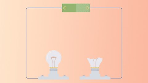
Parallel circuits
In a parallel circuit, different components are connected on different branches of the wire. If you follow the circuit diagram from one side of the cell to the other, you can only pass through all the different components if you follow all the branches.
In a parallel circuit, if a lamp breaks or a component is disconnected from one parallel wire, the components on different branches keep working. Unlike a series circuit, the lamps stay bright if you add more lamps in parallel.
When two components are connected in parallel, the current is shared between the components. The current is shared when it reaches the branches, then adds again where the branches meet.
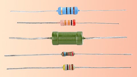
Resistance
The wires and the other components in a circuit reduces the flow of charge through them. This is called resistance.The unit of This tells us how difficult it is for current to flow through a circuit. The more resistance there is, the harder it is for current to flow. is the The unit of resistance., and it has the symbol ⊠(an uppercase Greek letter omega).
For example, a 2 ⊠component has a greater resistance than a 1 ⊠component, and will reduce the flow of charge through it more effectively.
Adding components
The resistance increases when you add more components in series. For example, the resistance of two lamps is greater than the resistance of one lamp, so less current will flow through them.
Calculating resistance
To find the resistance of a component, you need to measure:
- the potential difference across it
- the current flowing through it
The resistance is the ratio of potential difference to current. We use this equation to calculate resistance:
resistance = potential difference Ă· current
For example:
3 A flows through a 240 V lamp. What is the resistance of the lamp?
resistance = 240 Ă· 3 = 80 âŠ
If you plot a graph of current against potential difference for a wire, you get a straight line.
Conductors and insulators of electricity
Different materials have different resistances:
- an electrical A material which allows charge or heat to move easily through it. has a low resistance
- an electrical A material that does not allow current to flow through it easily, eg wood or glass. has a high resistance
You can easily find out which materials are conductors and which are insulators using a simple circuit.
You set up a series circuit with a cell, lamp and wires. Leave a gap in the circuit between two of the wires. Then connect the two wires using pieces of each material and see if the lamp lights up:
- it will light up if the material is a conductor
- it will not light up if the material is an insulator
The table lists some examples of conductors and insulators:
| Conductors | Insulators |
|---|---|
| Metal elements | Most non-metal elements eg sulphur, oxygen |
| Graphite (a form of carbon; a non-metal element) | Diamond (a form of carbon; a non-metal element) |
| Mixtures of metals, eg brass, solder | Plastic |
| Salt solution | Wood |
| Liquid calcium chloride | Rock |
Test your knowledge
Play the Atomic Labs game! game
Try out practical experiments in this KS3 science game.

More on Electricity
Find out more by working through a topic
- count8 of 11
- count9 of 11
- count10 of 11
- count11 of 11